 English
 العربية
 中文
中文
 Czech
Czech
 Dutch
Dutch
 Français
 Deutsch
 Español
 Português
 Svenska
 Magyar
Design for Manufacturing (DFM): The Complete Guide for EU & US Product Teams
- Design for Manufacturing (DFM) means designing a part so it is easy, reliable, and affordable to produce. You do it while you are still designing, not after the problems show up on the shop floor.
- The economics are hard to argue with. Roughly 70 to 80 percent of what a product will cost to make is decided during design, even though design is only a small slice of the budget. A tweak that is free on the CAD model can cost 10 to 100 times more once the tooling is cut.
- The levers are the same in every industry: use fewer parts, standardise what you can, shape the geometry to suit the process, only tighten the tolerances that matter, and pick the right material and process together.
- DFM is process specific. Injection moulding, sheet metal, CNC machining, and casting each have their own rules, and a good product engineering team applies them from the very first concept.
Two products can have the same specification, the same performance, and the same look, and still cost 30 percent more or less to make. The reason usually is not the factory. It is the design. When a part is drawn without much thought for how it will be moulded, machined, welded, or assembled, that extra cost rides along on every single unit for the life of the product. A few cents you never noticed on the model turns into the number that decides whether the whole programme makes money.
That is the problem Design for Manufacturing is here to solve. In this guide we will cover what DFM actually is, why it matters far more than most teams expect, the handful of principles that hold true for any process, the specific rules for the four most common manufacturing methods, a checklist you can take straight into your next design review, and how a DFM led product engineering partner turns a drawing into a part you can actually build.
What Is Design for Manufacturing (DFM)?
Design for Manufacturing, sometimes called design for manufacturability, is the practice of designing a part or product so it can be made predictably, at the quality you need, and at a sensible cost, using the process you actually intend to use. It is not a review you run at the end. It is a series of choices you make all the way through design, ideally with someone from manufacturing in the room from the first concept sketch.
You will often hear DFM mentioned alongside two close cousins, so it is worth keeping them straight:
- DFM (Design for Manufacturing) is about making each individual part easy to produce: easy to mould, machine, form, or cast.
- DFA (Design for Assembly) is about how the parts go together. It means using fewer parts, making them easy to insert, swapping fasteners for snap fits or built in features where you can, and error proofing (poka yoke) so a part can only go in the right way.
- DFMA (Design for Manufacturing and Assembly) puts the two together, because a change that makes one part simpler can easily make the assembly harder, and the other way around.
In practice, strong product teams run all three at once. Design, manufacturing, quality, and sourcing all look at the drawing together rather than passing it down a line one stage at a time. That is the difference between a design that has been drawn and a design that has been engineered to be built.
Why DFM Matters: The Economics of Early Design Decisions
The case for DFM is not about aesthetics or theory. It comes down to money, and it rests on two things we see on almost every programme.
Most of the cost is locked in before the first part is made
Study after study lands on the same number. The design phase, which usually eats up only a small part of the total budget, is where something like 70 to 80 percent of the eventual manufacturing cost gets committed. Once you have settled the geometry, the material, the tolerances, and the process, most of the unit cost is already fixed. Manufacturing just executes decisions that were, in effect, made months earlier in CAD. It is also why cost cutting that starts on the shop floor runs out of road so fast. The expensive calls were made long before anyone switched on a machine.
The cost of a change jumps at every stage
The second point is the familiar rule of ten. Fixing a design problem costs roughly ten times more at each stage you let it slip. A change is almost free while the part is still a model. It costs a bit more once you have a prototype, a lot more once production tooling is cut, and a frightening amount once parts are out in the field and you are looking at a recall or a retrofit.
"The cheapest change is the one you make on the model before the steel is cut. Every stage you put it off multiplies the cost, and once the tooling is done that multiplier stops being a rounding error and starts being the whole business case." Selva Barati Giri, PMP®
Put those two facts together and the conclusion writes itself. The single biggest point of leverage in the whole product lifecycle is the design phase, and DFM is how you use it. A proper DFM pass is not a tax on the schedule. It is the cheapest cost saving, quality improvement, and risk reduction you will ever get, precisely because it happens before the expensive decisions set hard.
Key Insight
DFM does not make a product cheaper by cutting corners. It makes it cheaper by stripping out the avoidable cost that a manufacturing blind design would have baked into every unit: wasted material, longer cycles, extra operations, tooling you did not need, and scrap from tolerances no function ever asked for.
The Core Principles of DFM
Whatever the industry or the process, good DFM keeps coming back to the same short list of principles. They are easy to say and hard to do really well.
1. Simplify and use fewer parts
Every part is a purchase order, an inspection, a stock line, an assembly step, and one more thing that can fail. The most dependable way to cut cost and lift quality is to design parts out. Combine two components into a single moulding, turn a bolted on bracket into a feature of the part next to it, or delete a sub assembly altogether. Fewer parts means less tooling, less assembly labour, fewer suppliers to chase, and fewer things that can go wrong.
2. Standardise parts, features, and materials
Bespoke is expensive. Standard fasteners, standard hole sizes, standard radii, standard materials, and shared components across a product family all bring tooling cost down, make sourcing simpler, and keep parts available. When a drawing calls for an odd drill size or an unusual thread pitch, it adds a premium to every unit for the life of the product, usually for no real benefit.
3. Design for the process you are using
A shape that is easy to machine can be impossible to mould, and the reverse is just as true. Matching the geometry to the process is the heart of DFM: uniform wall thickness for moulding, room for the tool to reach when machining, sensible relief cuts for sheet metal. The design has to respect how the process actually forms the material rather than fight it.
4. Be deliberate about tolerances
Tolerance is one of the biggest and most misread cost drivers in manufacturing. Every tolerance you tighten narrows the process window, pushes up scrap, and can force a slower cycle or an extra operation. The discipline is simple to state: tighten only what the function genuinely needs, and open up everything else. A drawing plastered with tight tolerances "to be safe" is not careful engineering. It is a standing cost premium and a quality risk. Clean detailed engineering and GD&T is where this gets sorted.
5. Choose the material and the process together
Material and process are really one decision, not two. The right pairing balances what the part has to do against cost, availability, and how easy it is to make. Reach for an over specified engineering polymer or an exotic alloy without a manufacturing conversation and you can double the part cost, or rule out the process you wanted in the first place. The best material choices are made with the process, the tooling, and the volume all in view.
6. Design for assembly and inspection
A part that is awkward to locate, grip, or measure is a part that costs more to assemble and check. Build in features that locate themselves, error proofing so a part cannot go in the wrong way, clear datum references for measurement, and access for gauges and fixtures. This is where DFM meets DFA, and where working with a team that also builds jigs, fixtures, and checking gauges quickly pays for itself.
DFM by Process: Moulding, Sheet Metal, CNC, and Casting
The principles above are universal, but how you apply them depends on the process. Here are the DFM points that matter most for the four most common methods. The exact numbers shift with material and geometry, so treat these as the questions a design review has to answer rather than fixed limits.
Injection moulding
Plastic injection moulding punishes poor DFM, because whatever you get wrong repeats across the whole life of the tool. The essentials:
- Keep the wall thickness even. Consistent walls cool evenly. Thick sections cool slowly and give you sink marks, voids, warp, and longer cycles. Where a thick section is unavoidable, core it out so the wall stays uniform.
- Add draft. Every face in the direction the part ejects needs a little draft, often around a degree per side and more for textured surfaces, so the part comes cleanly out of the tool.
- Watch ribs and bosses. Keep a rib to roughly half to two thirds of the nominal wall so it does not leave a sink mark on the show surface, and radius its base to ease the stress.
- Plan radii, gates, and the parting line. Avoid sharp inside corners, place gates so the tool fills evenly, and agree the parting line early, because it drives appearance, flash, and tooling cost.
Sheet metal fabrication
- Keep bend radii consistent. Use one internal bend radius, usually at least the material thickness, across the part so a single tool can form every bend.
- Give bends relief, and keep holes clear. Add relief cuts so bends do not tear, and keep holes and slots far enough from a bend that they do not distort when the metal is formed.
- Standardise the features. Consistent hole sizes, minimum flange lengths, and standard gauges cut tooling changes and keep the nesting tight, which is what drives material use.
- Keep operations to a minimum. Every extra bend, weld, or secondary step adds cost and stacks up tolerance. Fold the complexity out of the flat pattern wherever you can.
CNC machining
- Mind tool access and inside radii. An inside corner can never be sharper than the tool that cuts it, so give internal radii a standard end mill can reach. Deep, narrow pockets need long, thin tools that chatter and snap, so keep the depth sensible against the width.
- Cut down the setups. Features that force you to re fixture the part in several orientations add cost and invite alignment error. Design so most of the work can be reached in one setup.
- Use standard sizes and avoid thin walls. Stick to standard drill and thread sizes, and steer clear of thin, unsupported walls that flex under the cutter.
Casting and die casting
- Keep sections even and fillet the corners. As with moulding, uneven sections shrink unevenly and leave porosity. Blend the transitions with fillets and radii.
- Add draft and place the parting line well. Draft the vertical faces and set the parting line to keep flash and finishing to a minimum.
- Avoid heavy, isolated lumps of material. Thick, isolated sections form shrinkage cavities, so spread the material out or add cores to keep the sections balanced.
Fabrication, moulding, and assembly across all of these processes is exactly what Ledvore's contract manufacturing and assembly network covers, so the manufacturability feedback is grounded in what a real production line can actually hold.
A Practical DFM Checklist
Use this as a first pass in any design review. Wherever the honest answer is "we are not sure," that is exactly where the DFM conversation needs to go.
- Part count. Can any two parts become one? Can a fastener become a feature? Can a sub assembly disappear?
- Process fit. Does the geometry suit the process, with even walls and draft for moulding, tool access for machining, and relief for sheet metal?
- Tolerances. Is every tight tolerance earning its place? Has everything non critical been opened up?
- Material and process. Is the pairing confirmed for the target volume, cost, and availability?
- Standardisation. Are holes, threads, radii, and components standard and shared across the family wherever they can be?
- Assembly and inspection. Can the part be located, error proofed, gripped, and measured without special tooling?
- Supplier capability. Has a real manufacturer confirmed they can hold the design as drawn, at volume?
Where DFM Fits in Product Development
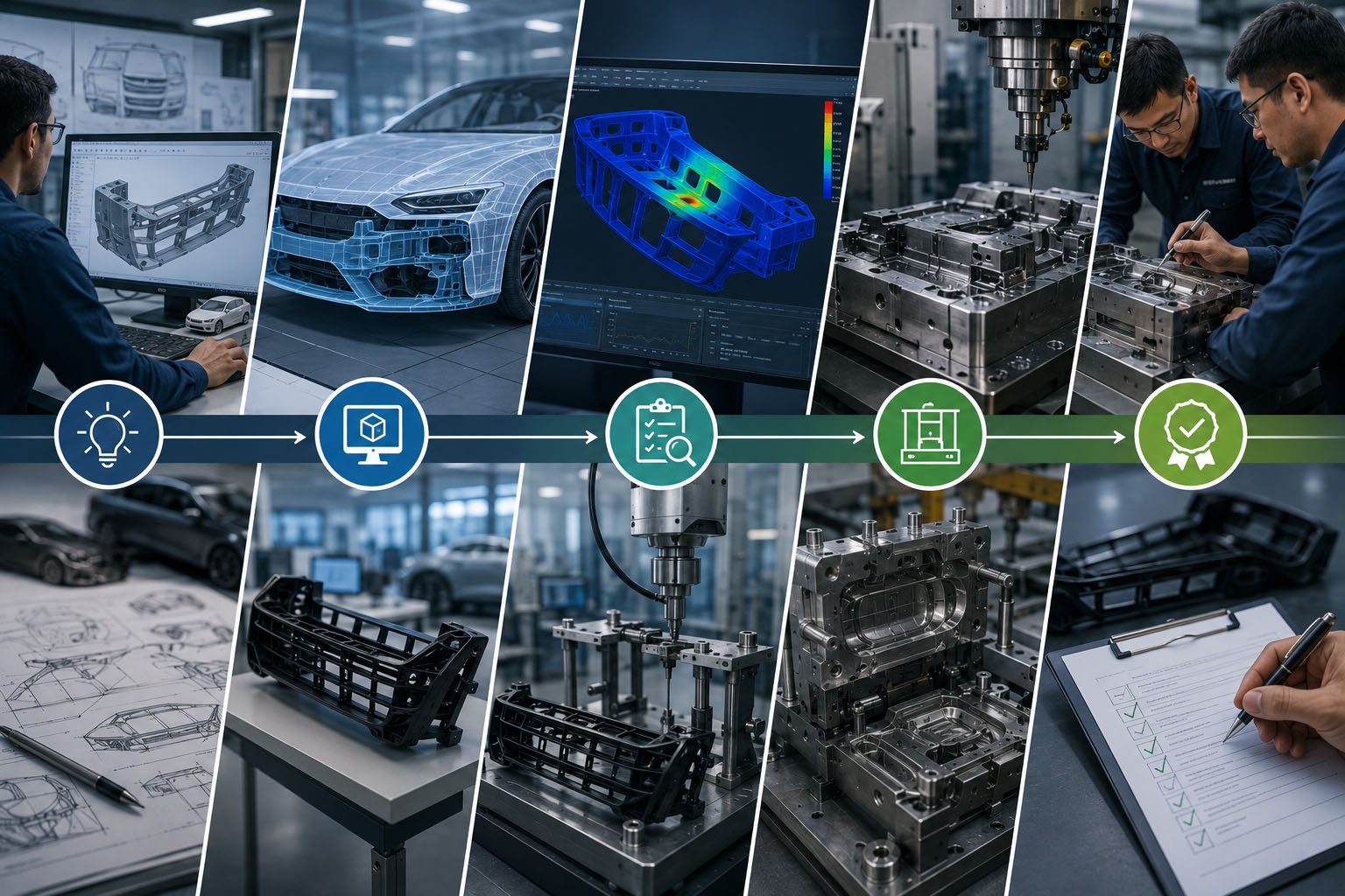
DFM is not a single gate. It is a thread that runs through the whole process and tightens as the design matures. A well run product engineering programme applies it at every stage:
- Concept and product development. The earliest and highest leverage point. Part count, process choice, and the overall architecture are set here.
- Simulation and engineering analysis. Structural, thermal, flow, and mould fill simulation prove the design both performs and manufactures before any metal is cut, so the risk is closed out on the model.
- DFM optimisation. A dedicated pass to take out manufacturability risk: walls, draft, tolerances, tool access, and cost drivers.
- Detailed engineering and GD&T. The manufacturability intent gets written down properly in drawings and geometric tolerancing, so the supplier builds what the designer meant.
- Prototyping and validation. Real parts confirm the DFM decisions, and anything left over is caught while change is still cheap.
- Process validation and PPAP. The design moves onto a controlled, repeatable process. This is where manufacturing process engineering, part validation, and PPAP take over and prove the process before full production.
Ledvore's product engineering service is built around exactly these stages, from concept and simulation through DFM, detailed engineering, and rapid prototyping, so manufacturability is designed in from the first concept instead of being discovered at the tool trial.
Five Common DFM Mistakes
Most manufacturability problems trace back to the same few mistakes. Spotting them early is half the job.
- Leaving DFM too late. Running a DFM review after the design is frozen throws away almost all of its value, because by then the expensive decisions are already made.
- Over tolerancing. Tightening everything "to be safe" is the most common and most expensive DFM mistake there is. It adds scrap and cost to every unit for no real gain.
- Designing for one process, then switching. A shape optimised for machining rarely moves cleanly to moulding or casting. When the process changes, the design has to change with it.
- No manufacturing input. Design in isolation from the people who will build the part and you are guaranteeing rework. Manufacturability is a conversation, not a box you tick at the end.
- Ignoring what the supplier can actually do. A design is only manufacturable if a real supplier can hold it at volume. DFM done against a generic capability, rather than the actual line, misses the constraints that count.
How a DFM Led Product Engineering Partner Works
For a lot of manufacturers in Europe and the US, the problem is not knowing that DFM matters. It is finding the engineering bandwidth to apply it properly on every programme while the senior people are already stretched thin. This is where a structured offshore product engineering partner changes the maths.
The model works because DFM is exactly the kind of well defined, high value engineering that an integrated offshore team does well: concept development, CAD modelling, simulation and FEA, DFM optimisation, detailed engineering with GD&T, reverse engineering, and prototyping. Ledvore delivers all of this through India's deep engineering talent, at a cost that lets manufacturers apply full DFM discipline to programmes that would otherwise get rushed. It is the same extended engineering team model that closes the gap between engineering and execution we have written about elsewhere.
The important part is that the feedback is grounded in what the line can really do. Because the same partner runs a manufacturing and tooling network, the manufacturability advice reflects what the production line can actually hold. That is the difference between a DFM report that looks good and a design that runs.
Conclusion
DFM is the highest leverage work in product development because it acts at the exact moment cost, quality, and risk are decided, and before any of those decisions get expensive to change. It is not a limit on good design. It is what makes good design pay off. A product engineered to be built is cheaper to make, quicker to launch, more reliable in the field, and easier to scale.
If your team is carrying more product programmes than it has the bandwidth to properly DFM, that is exactly the gap Ledvore is built to close. Our product engineering practice brings manufacturability discipline from concept to production readiness, so the cost you would have found at the tool trial gets designed out on the model instead.
Frequently Asked Questions
Common questions about Design for Manufacturing and manufacturability led product engineering.